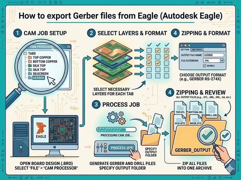
Export Gerber files from Eagle
Exporting Gerber files from Autodesk Eagle is a key step before starting تصنيع ثنائي الفينيل متعدد الكلور و تجميع ثنائي الفينيل متعدد الكلور. Gerber files contain all the necessary data for fabricating your PCB, including copper layers, solder mask, silkscreen, and drill information.
Below is a step-by-step guide to help you correctly generate Gerber files for تجميع SMT والإنتاج.
Open your PCB design
Start by opening your completed board file (.brd) in Autodesk Eagle. Make sure your design is finalized and all components are properly placed and routed.
It’s recommended to run a Design Rule Check (DRC) before exporting to ensure there are no layout errors that could affect تجميع ثنائي الفينيل متعدد الكلور.
Open the CAM processor
In the top menu, go to
File → CAM Processor
The CAM Processor is the tool used to generate Gerber files for تصنيع ثنائي الفينيل متعدد الكلور. It allows you to select layers and configure output settings.
Load a CAM job file
Eagle usually includes default CAM job files.
Click File → Open → Job, then select a standard job such as:
gerber.cam
This will automatically load predefined settings for common Gerber outputs, suitable for most تجميع ثنائي الفينيل متعدد الكلور المتطلبات.
Configure Gerber layers
Ensure the correct layers are selected for export. Typical layers include:
- Top Copper (Top)
- Bottom Copper (Bottom)
- Solder Mask Top/Bottom
- Silkscreen Top/Bottom
- Board Outline (Dimension layer)
بالنسبة لـ تجميع SMT, accurate solder mask and silkscreen layers are especially important.
Set output format
Make sure the output format is set correctly:
- Format: RS-274X (standard Gerber format)
- Units: mm or inch (match your design settings)
- Resolution: usually 2:5 or 2:6
These settings ensure compatibility with most تصنيع ثنائي الفينيل متعدد الكلور suppliers.
Generate Gerber files
Click the Process Job button.
Eagle will generate a set of Gerber files, typically including:
- .GTL (Top Layer)
- .GBL (Bottom Layer)
- .GTS / .GBS (Solder Mask)
- .GTO / .GBO (Silkscreen)
- .GKO or .GML (Board Outline)
These files are essential for both fabrication and تجميع ثنائي الفينيل متعدد الكلور.
Export drill files
Gerber files do not include drill data, so you must export it separately.
Go to:
File → CAM Processor → Drill data (Excellon format)
This file contains hole sizes and locations, which are critical for تصنيع ثنائي الفينيل متعدد الكلور.
Verify Gerber files
Before sending files to your manufacturer, always verify them using a Gerber viewer.
Check that:
- All layers are aligned correctly
- Board outline is accurate
- No missing pads or traces
- Text and markings appear properly
This step helps prevent costly errors in تجميع ثنائي الفينيل متعدد الكلور.
Package files for submission
Finally, compress all Gerber and drill files into a single ZIP archive.
Include:
- ملفات جربر
- Drill file
- Readme or notes (if needed)
You can now send this package to your تصنيع ثنائي الفينيل متعدد الكلور أو تجميع ثنائي الفينيل متعدد الكلور supplier for quotation and production.
الخاتمة
Exporting Gerber files from Autodesk Eagle is a straightforward process when using the CAM Processor with the correct settings. Proper file preparation ensures smooth تجميع SMT, reduces manufacturing errors, and speeds up your project timeline.
هل تبحث عن حل موثوق لتجميع ثنائي الفينيل متعدد الكلور؟ انقر أدناه لطلب عرض الأسعار الآن.
نحن نوفر خدمات تجميع ثنائي الفينيل متعدد الكلور الاحترافية بما في ذلك SMT وDIP وحلول تسليم المفتاح الكاملة.
✔ إتاحة اتفاقية عدم الإفشاء ✔ عرض أسعار سريع في غضون 24 ساعة ✔ مصنع معتمد من ISO ✔ خدمة PCB و PCBA الشاملة