Export Gerber files from Eagle
Exporting Gerber files from Autodesk Eagle is a key step before starting PCB 제조 그리고 PCB 어셈블리. Gerber files contain all the necessary data for fabricating your PCB, including copper layers, solder mask, silkscreen, and drill information.
Below is a step-by-step guide to help you correctly generate Gerber files for SMT 어셈블리 및 프로덕션.
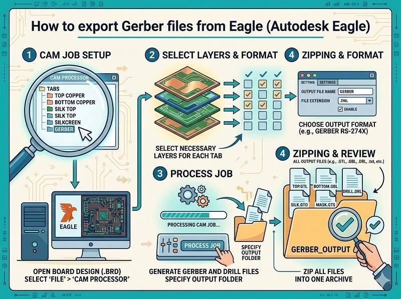
Open your PCB design
Start by opening your completed board file (.brd) in Autodesk Eagle. Make sure your design is finalized and all components are properly placed and routed.
It’s recommended to run a Design Rule Check (DRC) before exporting to ensure there are no layout errors that could affect PCB 어셈블리.
Open the CAM processor
In the top menu, go to
File → CAM Processor
The CAM Processor is the tool used to generate Gerber files for PCB 제조. It allows you to select layers and configure output settings.
Load a CAM job file
Eagle usually includes default CAM job files.
Click File → Open → Job, then select a standard job such as:
gerber.cam
This will automatically load predefined settings for common Gerber outputs, suitable for most PCB 어셈블리 요구 사항.
Configure Gerber layers
Ensure the correct layers are selected for export. Typical layers include:
- Top Copper (Top)
- Bottom Copper (Bottom)
- Solder Mask Top/Bottom
- Silkscreen Top/Bottom
- Board Outline (Dimension layer)
For SMT 어셈블리, accurate solder mask and silkscreen layers are especially important.
Set output format
Make sure the output format is set correctly:
- Format: RS-274X (standard Gerber format)
- Units: mm or inch (match your design settings)
- Resolution: usually 2:5 or 2:6
These settings ensure compatibility with most PCB 제조 suppliers.
Generate Gerber files
Click the Process Job button.
Eagle will generate a set of Gerber files, typically including:
- .GTL (Top Layer)
- .GBL (Bottom Layer)
- .GTS / .GBS (Solder Mask)
- .GTO / .GBO (Silkscreen)
- .GKO or .GML (Board Outline)
These files are essential for both fabrication and PCB 어셈블리.
Export drill files
Gerber files do not include drill data, so you must export it separately.
Go to:
File → CAM Processor → Drill data (Excellon format)
This file contains hole sizes and locations, which are critical for PCB 제조.
Verify Gerber files
Before sending files to your manufacturer, always verify them using a Gerber viewer.
Check that:
- All layers are aligned correctly
- Board outline is accurate
- No missing pads or traces
- Text and markings appear properly
This step helps prevent costly errors in PCB 어셈블리.
Package files for submission
Finally, compress all Gerber and drill files into a single ZIP archive.
Include:
- 거버 파일
- Drill file
- Readme or notes (if needed)
You can now send this package to your PCB 제조 또는 PCB 어셈블리 supplier for quotation and production.
결론
Exporting Gerber files from Autodesk Eagle is a straightforward process when using the CAM Processor with the correct settings. Proper file preparation ensures smooth SMT 어셈블리, reduces manufacturing errors, and speeds up your project timeline.
신뢰할 수 있는 PCB 어셈블리 솔루션을 찾고 계신가요? 지금 견적을 요청하려면 아래를 클릭하세요.
당사는 SMT, DIP 및 전체 턴키 솔루션을 포함한 전문 PCB 조립 서비스를 제공합니다.
NDA 가능 ✔ 24시간 이내 빠른 견적 ✔ ISO 인증 공장 ✔ 원스톱 PCB 및 PCBA 서비스