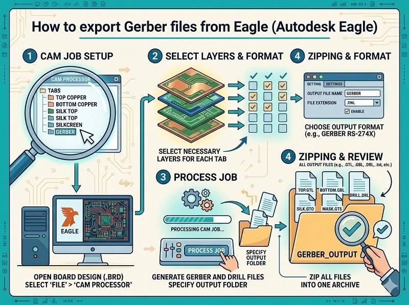
Export Gerber files from Eagle
Exporting Gerber files from Autodesk Eagle is a key step before starting Fabrication de circuits imprimés et Assemblage du circuit imprimé. Gerber files contain all the necessary data for fabricating your PCB, including copper layers, solder mask, silkscreen, and drill information.
Below is a step-by-step guide to help you correctly generate Gerber files for Assemblage SMT et la production.
Open your PCB design
Start by opening your completed board file (.brd) in Autodesk Eagle. Make sure your design is finalized and all components are properly placed and routed.
It’s recommended to run a Design Rule Check (DRC) before exporting to ensure there are no layout errors that could affect Assemblage du circuit imprimé.
Open the CAM processor
In the top menu, go to
File → CAM Processor
The CAM Processor is the tool used to generate Gerber files for Fabrication de circuits imprimés. It allows you to select layers and configure output settings.
Load a CAM job file
Eagle usually includes default CAM job files.
Click File → Open → Job, then select a standard job such as:
gerber.cam
This will automatically load predefined settings for common Gerber outputs, suitable for most Assemblage du circuit imprimé exigences.
Configure Gerber layers
Ensure the correct layers are selected for export. Typical layers include:
- Top Copper (Top)
- Bottom Copper (Bottom)
- Solder Mask Top/Bottom
- Silkscreen Top/Bottom
- Board Outline (Dimension layer)
Pour Assemblage SMT, accurate solder mask and silkscreen layers are especially important.
Set output format
Make sure the output format is set correctly:
- Format: RS-274X (standard Gerber format)
- Units: mm or inch (match your design settings)
- Resolution: usually 2:5 or 2:6
These settings ensure compatibility with most Fabrication de circuits imprimés suppliers.
Generate Gerber files
Click the Process Job button.
Eagle will generate a set of Gerber files, typically including:
- .GTL (Top Layer)
- .GBL (Bottom Layer)
- .GTS / .GBS (Solder Mask)
- .GTO / .GBO (Silkscreen)
- .GKO or .GML (Board Outline)
These files are essential for both fabrication and Assemblage du circuit imprimé.
Export drill files
Gerber files do not include drill data, so you must export it separately.
Go to:
File → CAM Processor → Drill data (Excellon format)
This file contains hole sizes and locations, which are critical for Fabrication de circuits imprimés.
Verify Gerber files
Before sending files to your manufacturer, always verify them using a Gerber viewer.
Check that:
- All layers are aligned correctly
- Board outline is accurate
- No missing pads or traces
- Text and markings appear properly
This step helps prevent costly errors in Assemblage du circuit imprimé.
Package files for submission
Finally, compress all Gerber and drill files into a single ZIP archive.
Include:
- Fichiers Gerber
- Drill file
- Readme or notes (if needed)
You can now send this package to your Fabrication de circuits imprimés ou Assemblage du circuit imprimé supplier for quotation and production.
Conclusion
Exporting Gerber files from Autodesk Eagle is a straightforward process when using the CAM Processor with the correct settings. Proper file preparation ensures smooth Assemblage SMT, reduces manufacturing errors, and speeds up your project timeline.
Vous recherchez une solution d'assemblage de circuits imprimés fiable ? Cliquez ci-dessous pour demander un devis.
Nous fournissons des services professionnels d'assemblage de circuits imprimés, y compris SMT, DIP et des solutions complètes clé en main.
✔ NDA disponible ✔ Devis rapide sous 24 heures ✔ Usine certifiée ISO ✔ Service unique de PCB et PCBA