An Assembly Drawing
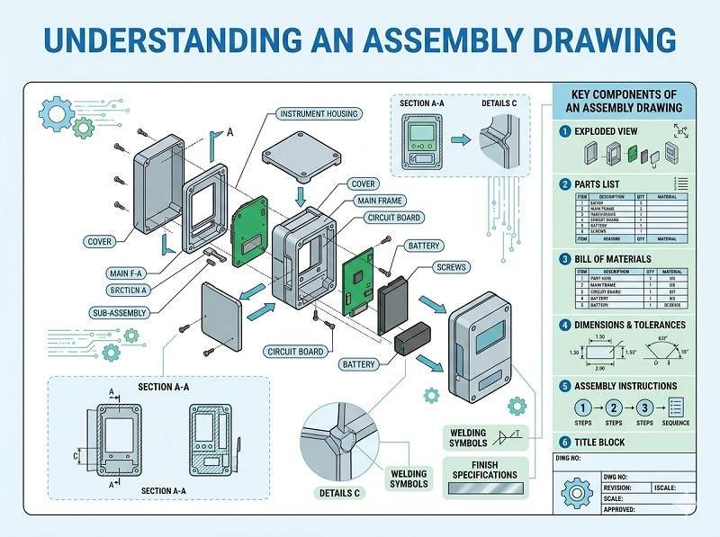
An assembly drawing is a visual document used in Montaje de PCB that shows how electronic components are placed and oriented on a printed circuit board. It provides a clear graphical reference for engineers, technicians, and inspectors during the Montaje SMT and final assembly process.
This drawing helps ensure that every component is installed correctly according to the design intent.
What Information Does an Assembly Drawing Include
An assembly drawing typically contains detailed placement and identification information for all components on the PCB.
Common elements include:
- Reference designators (e.g., R1, C1, U1)
- Component outlines and locations
- Polarity markings (for diodes, capacitors, ICs, etc.)
- Pin 1 indicators for integrated circuits
- Board outline and dimensions
- Notes for special assembly instructions
These details are essential for accurate and consistent Montaje de PCB.
Types of Assembly Drawings
There are usually two types of assembly drawings provided.
Top assembly drawing shows components mounted on the top side of the PCB.
Bottom assembly drawing shows components placed on the underside of the board.
For double-sided boards, both drawings are necessary to guide Montaje SMT and other processes.
Role in PCB Assembly
Assembly drawings play a key role in guiding manual and automated processes.
They are used by operators for component verification and by quality inspectors to check whether components are correctly placed and oriented.
In cases where automated data (like pick and place files) is unclear or needs validation, the assembly drawing serves as a reliable visual reference.
Importance in SMT Assembly
En Montaje SMT, most placement is automated, but assembly drawings are still important.
They help verify machine programming, confirm correct polarity, and assist in troubleshooting placement issues.
For prototypes and low-volume production, where some manual work is involved, assembly drawings are especially critical.
Assembly Drawing vs Other Files
An assembly drawing works alongside other PCB Assembly files.
The BOM defines what components are needed.
The pick and place file defines where components go in machine-readable format.
The assembly drawing visually shows component placement and orientation.
Together, these files ensure a complete and accurate assembly process, especially in Montaje de PCB llave en mano.
Use in Turnkey PCB Assembly
En Montaje de PCB llave en mano, the assembly drawing helps the manufacturer interpret design intent clearly.
It supports component sourcing verification, placement accuracy, and inspection processes. It also helps avoid errors when dealing with complex boards or special requirements.
Common Mistakes to Avoid
Poorly prepared assembly drawings can lead to confusion and errors.
Missing polarity markings may cause incorrect installation of components.
Unclear or overlapping reference designators can make identification difficult.
Inconsistent information compared to BOM or PCB layout files can lead to assembly issues.
Ensuring clarity and consistency is essential.
Best Practices for Assembly Drawings
To create effective assembly drawings, follow these best practices.
Use clear and legible reference designators.
Include polarity and pin 1 indicators for all relevant components.
Provide separate drawings for top and bottom layers.
Avoid clutter and ensure good readability.
Keep the drawing consistent with BOM and layout data used in Fabricación de PCB.
Conclusión
An assembly drawing is a vital document in PCB Assembly, providing a clear visual guide for component placement and orientation. It supports both automated and manual processes in Montaje SMT and helps ensure accuracy and quality.
When combined with BOM, pick and place files, and Gerber data, assembly drawings play an essential role in achieving reliable results in modern Fabricación de PCB y Montaje de PCB llave en mano.
Fast, reliable, and cost-effective PCB assembly solutions. Request your quote now.
Ofrecemos servicios profesionales de ensamblaje de placas de circuito impreso, incluyendo SMT, DIP y soluciones completas llave en mano.
✔ NDA disponible ✔ Presupuesto rápido en 24 horas ✔ Fábrica certificada ISO ✔ Servicio integral de PCB y PCBA.