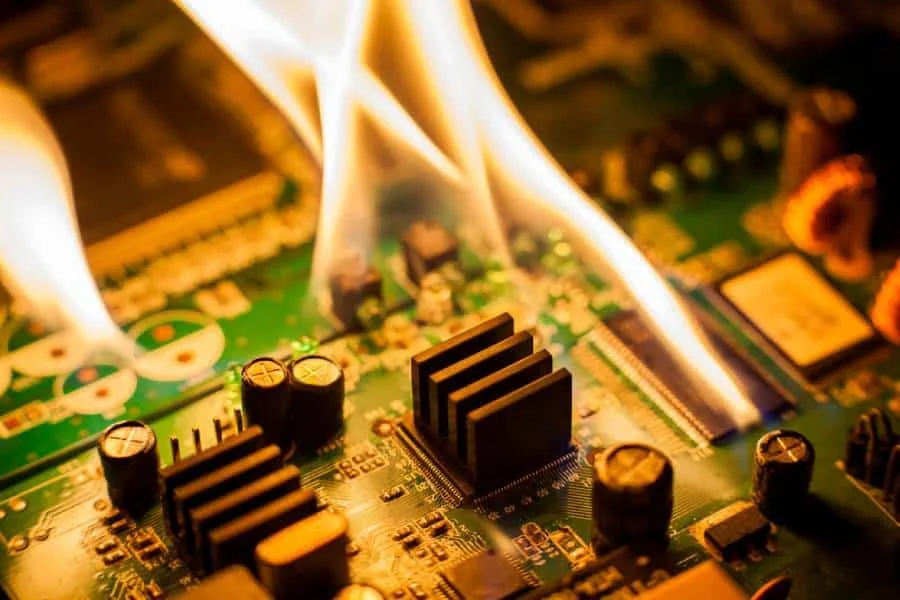
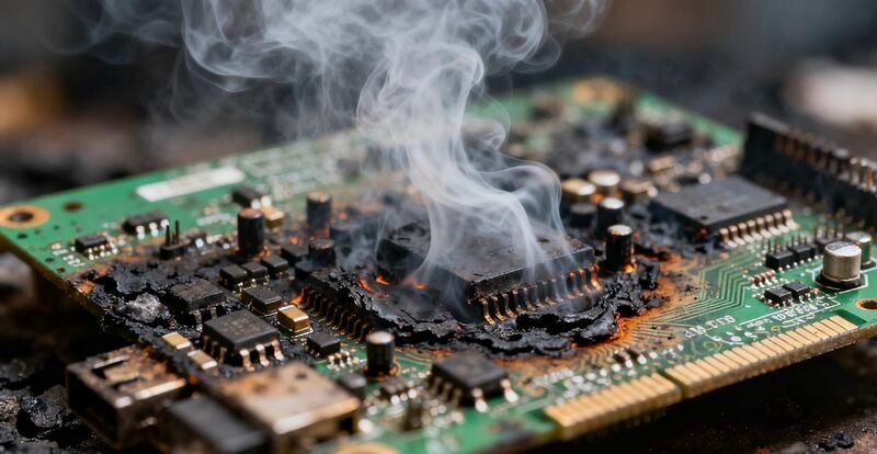
The Hidden Threat to Product Reliability
In modern electronics, the trend towards miniaturization and increased functionality has led to higher power density on the PCBA. Thermal management is no longer an afterthought—it is a critical design and manufacturing challenge. Excessive heat accumulation in components like CPUs, FPGAs, and Power Regulators can lead to performance throttling, accelerated component aging, and ultimately, catastrophic product failure.
Mastering thermal management requires seamless collaboration between design engineering and the PCBA manufacturing process. This article outlines the four core strategies needed to effectively manage heat, ensuring product longevity and reliability.

Strategy 1: PCB Layout and Material Selection (Design Phase)
Heat mitigation starts with the structure of the PCB itself.
- 1. Copper Thickness and Trace Width: Copper is an excellent thermal conductor. Increasing copper weight (e.g., from 1 oz to 2 oz or even heavy copper) and widening power and ground traces helps spread heat laterally across the board.
- 2. Thermal Vias: These are small, non-electrical vias placed directly beneath or adjacent to heat-dissipating components (especially BGA/QFN). They act as direct conduits, transferring heat from the top layer down to internal ground/power planes or the bottom layer, which functions as a heatsink.
- 3. High $T_g$ Laminates: For high-power applications, standard FR4 materials may not suffice. Using laminates with a high glass transition temperature ($T_g$) prevents the board from softening, delaminating, or expanding excessively under operational thermal stress.
Strategy 2: Component Placement and Spreading
Smart component placement can reduce localized hotspots.
- 1. Spreading High-Power Components: Avoid clustering multiple high-power components together. Spreading them out allows for heat dissipation over a larger area, reducing the localized thermal load on the board.
- 2. Utilizing Thermal Relief: Ensure that component placement is optimized for the attachment of external heat sinks or fans in the final enclosure. Leave adequate clearance and ensure mounting holes are precisely manufactured.
- 3. Edge Placement: Placing hot components closer to the PCB edge facilitates heat transfer to the enclosure or chassis, using the external structure as an auxiliary heatsink.
Strategy 3: Specialized Assembly and Attachment (Manufacturing Phase)
Manufacturing techniques must ensure efficient thermal contact for attached components.
- 1. Void-Free Solder Joints for Bottom-Terminated Components: Components like QFNs, which dissipate heat through a thermal pad on their underside, require void-free solder joints in this area. Voids reduce the effective contact area, trapping heat.
- Manufacturer’s Role: Using specialized solder paste stencils (often with unique aperture designs) and controlling the reflow profile precisely is critical to achieving a high-quality, thermally efficient solder joint.
- 2. Thermal Interface Material (TIM) Application: When external heat sinks are used, applying the Thermal Interface Material (TIM) (e.g., thermal grease or pads) must be precise. Automated dispensing ensures the correct thickness and complete coverage, maximizing thermal conductivity across the interface.
Strategy 4: Verification and Validation
Manufacturing quality must be verified through thermal inspection.
- 1. Thermal Profiling and Simulation: Advanced suppliers use Finite Element Analysis (FEA) software during the Design for Manufacturability (DFM) review to predict potential hotspots before manufacturing begins.
- 2. Infrared Thermography (Thermal Imaging): During the functional testing (FCT) phase, Infrared (IR) cameras are used to measure the actual surface temperature distribution on the assembled PCBA under load. This non-contact method confirms that the heat mitigation strategies are effective and that no components are exceeding their maximum operating temperature.
Conclusion and Call to Action
Effective PCBA thermal management requires expertise spanning laminate selection, layout geometry, and specialized assembly techniques. Choosing a PCBA partner with deep engineering capabilities and advanced thermal inspection tools is essential for guaranteeing the long-term reliability of your high-power product.
Don’t let heat be your product’s undoing. Contact our engineering team to conduct a comprehensive thermal analysis (FEA) on your design today.