Testing – The Uncompromisable Quality Gate
In PCBA manufacturing, the testing phase is the ultimate quality gate, ensuring that the assembled board not only meets specifications but also performs reliably in the final product. The choice of testing methodology—primarily between Functional Test (FCT) and In-Circuit Test (ICT)—is a critical decision that significantly impacts the cost, timeline, failure detection rate, and long-term quality of your batch.
Choosing the right test strategy depends on your product’s complexity, production volume, budget, and the consequences of failure. This article dissects the strengths, weaknesses, and ideal applications for both FCT and ICT, helping you partner with your PCBA supplier to define the optimal testing plan.
Test Method 1: In-Circuit Test (ICT) – The Comprehensive Detective
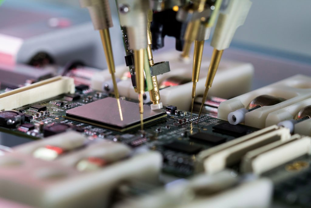
ICT is a fixture-based testing method that verifies the integrity and value of every single component and connection on the board.
- What it Checks: Continuity checks (shorts/opens), component presence, resistor/capacitor/diode values, and often component orientation. It physically accesses all test points using a “bed-of-nails” fixture.
- Strengths:
- High Fault Isolation: ICT can pinpoint the exact failing component or solder bridge, making rework extremely fast and efficient.
- Speed: Fast execution, typically testing thousands of points in seconds, ideal for high-volume production.
- Coverage: Excellent structural coverage (up to 99% of manufacturing defects).
- Weaknesses:
- High Initial Cost: Requires expensive, custom-built test fixtures and programming for each board, making it impractical for low-volume or prototyping runs.
- Limited Functional Check: It verifies what the circuit is, not what the circuit does. It cannot catch dynamic or timing-related defects.
- Ideal Application: High-volume consumer electronics, automotive ECUs, and products with fixed designs where failure diagnosis speed is paramount.
Test Method 2: Functional Test (FCT) – The End-User Simulator

FCT simulates the product’s final operating environment, verifying that the PCBA performs its intended function as designed.
- What it Checks: Inputs/outputs (I/O), power consumption, processor communication, memory access, and overall system functionality (e.g., “Does the Wi-Fi module transmit data?” “Does the LED blink when commanded?”).
- Strengths:
- System-Level Validation: Catches complex, dynamic, and timing-related faults that ICT misses. It confirms the entire system works as specified.
- Lower Initial Cost: FCT fixtures are often simpler and cheaper to build than ICT fixtures, making it suitable for low-to-medium volume, prototypes, and NPI.
- Weaknesses:
- Difficult Fault Isolation: When a test fails, FCT can only point to the general functional block (e.g., “The RF signal is weak”), not the specific faulty component. Diagnosis requires more time and skilled technicians.
- Slower Execution: Testing sequence is longer and more complex than ICT.
- Ideal Application: High-reliability industrial equipment, complex prototypes, aerospace components, and products requiring rigorous performance validation.
Choosing the Optimal Strategy: Volume, Cost, and Complexity
The decision should be made collaboratively with your PCBA partner based on these factors:
| Factor | ICT Strategy | FCT Strategy | Combined (Hybrid) Strategy |
| Production Volume | High (10,000+ units) | Low to Medium (100–5,000 units) | Medium to High |
| Initial Investment | High (Costly Fixtures) | Low to Medium (Simpler Fixtures) | Highest |
| Primary Goal | Fast, detailed structural defect isolation; High throughput. | System-level performance validation; Ensuring end-user experience. | Max coverage + Max throughput |
| Design Complexity | Moderate (Relatively few test points needed) | High (Requires dynamic checks) | High (Non-negotiable reliability) |
| Key Requirement | Fast rework/diagnosis | Final performance assurance | Critical systems (Medical, Defense) |
Partnering for Testability (DFT)
The most efficient strategy involves Design for Testability (DFT), integrating test requirements into the PCB layout from the outset (as discussed in T7).
- Supplier’s Role in DFT: Your PCBA supplier should work with you during the DFM phase to:
- Identify and place adequate test points for ICT (if chosen).
- Define necessary test access connectors for FCT.
- Develop the Test Program (the software sequence) concurrently with the PCBA assembly, accelerating the NPI timeline.
- The Hybrid Approach: For critical products, a Hybrid Test combines the structural flaw detection of ICT with the performance validation of FCT, providing the best of both worlds, though at the highest cost.
Conclusion and Call to Action
The right testing strategy is not a matter of “more is better,” but of “optimal coverage for the cost.” An experienced PCBA supplier will guide you beyond the basic FCT/ICT debate to design a customized testing plan that minimizes rework costs and maximizes your confidence in the final product’s reliability.
Ensure your product is flawless from the inside out. Consult our engineering team today to develop a customized DFT and testing strategy that meets your budget and quality demands.